
Where Q T is the total heat load and U is the mean overall heat transfer coefficient. A possible configuration for low pressure drop is the J-shell with double segmental baffles. It is possible to use other TEMA shell types, such as the J-type, to minimize pressure drop. A typical vent location is shown in Figure 3. The vapor vent should be situated at the end of the vapor flow path. Plain tubes are generally used, though low-finned tubes can be used to obtain increased heat transfer rates when the condensate resistance to heat transfer with plain tubes is significantly greater than that of the coolant. The number of tube passes is determined by the required coolant velocity. The size of the baffle cut is generally chosen such that the vapor velocity in the baffle window is roughly equal to that in the overlap zone between the baffle plates. Thus, if adequate pressure drop is available, it may be possible to reduce baffle spacing to obtain increased heat transfer rates. High vapor velocities can reduce resistance to heat transfer through the shear effect on the condensate film. The resistance to heat transfer due to the presence of noncondensing gases is inversely proportional to the vapor velocity. Pressure drop depends on vapor velocity, and hence on baffle spacing The tubes must be supported to avoid tube vibration This is a simple method of condensing a vapor, but there are practical problems associated with generating a good distribution of bubbles of small size, which are required for efficient heat transfer. The sparge pipe consists of a pipe with holes for injecting bubbles of vapor into a pool of liquid. The liquid is usually injected in counterflow to the vapor. A jet of liquid is injected into a pipeline carrying vapor via a small bore pipe and a nozzle located at the center line.

This is a device in which a jet of liquid is directed into a vapor stream, usually with the objective of desuperheating the vapor. The disadvantage of this type of condenser is that the pressure drop is higher than in other types of direct-contact condenser.

Liquid is supplied to the top of the column and vapor is supplied to the bottom. A packed column may consist of tightly-packed metal rings to increase the interfacial area for heat transfer. (Flooding is an unstable condition when the vapor flow is such that the downward flow of condensate is interrupted and held up.) It has the advantage of countercurrent flow of vapor and coolant, though care must be taken to avoid flooding. The vapor is supplied to the bottom of the column.
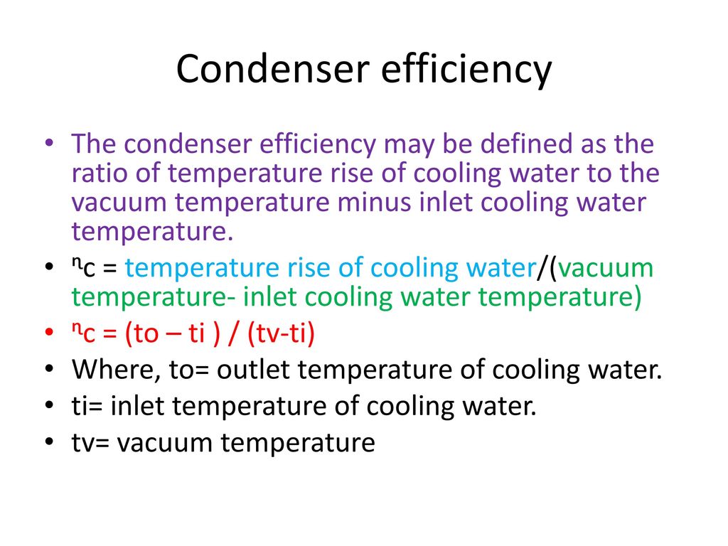
#Condenser efficiency calculation series
This is similar to the spray condenser, except that the coolant is directed to flow over a series of trays in a column (see Figure 2). It is important that the spray nozzles and vessel are designed to produce a fine spray of liquid (to give a large interfacial area for heat transfer), and a long enough residence time of liquid droplets in the vessel. The coolant is sprayed, using nozzles, into a vessel to which the vapor is supplied. Because chilled water pipes operate below ambient temperatures, proper insulation can protect these pipes from moisture and condensation problems such as corrosion and mold growth.The Spray Condenser.


 0 kommentar(er)
